


DJ Sures' Robots
Embark on a captivating journey where vintage toys are reborn as futuristic companions in "Teaching Old Toys New Tricks." Our visionary founder, DJ Sures, transforms forgotten relics into personalized robot pals using the powerful Synthiam platform and cutting-edge technologies. Picture your favorite childhood toys brought to life, responding to commands and learning new tricks – a perfect blend of nostalgia and innovation. Each creation is a unique work of art, a testament to DJ Sures' craftsmanship, making these robot companions not just novelties but partners in adventure and fun. Join us in this enchanting fusion of past and present, where old toys find new life as cherished and interactive friends.
robot
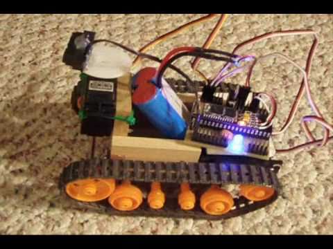
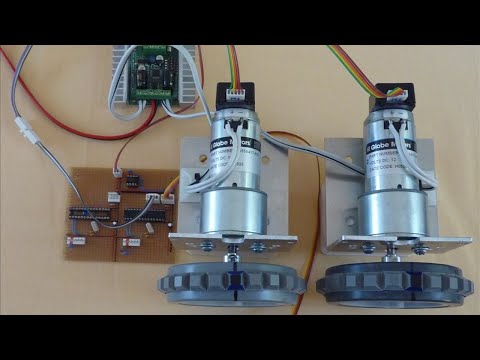
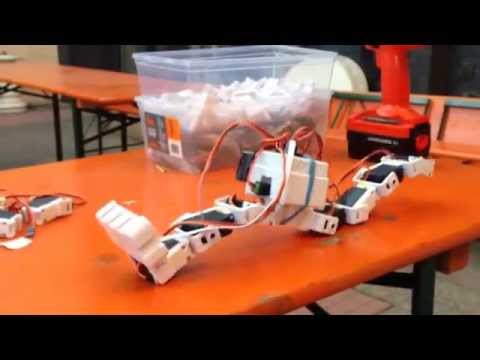
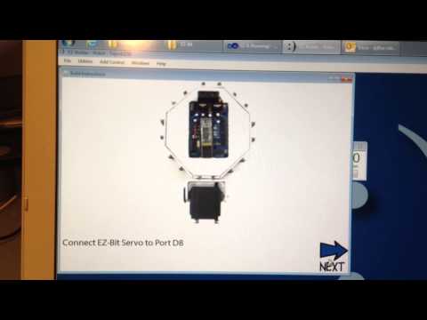
DJs Tamiya Bulldozer Robot
This is a tutorial on how to modify the Tamiya Bulldozer to be driven by modified servos rather than the DC motorset. The software controlling this robot is ARC....
DJ Sures |
live hack

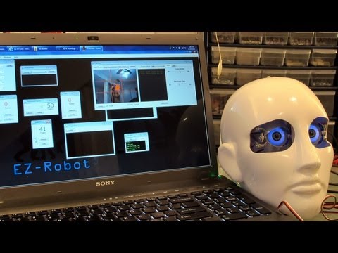
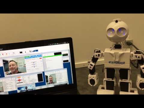
DJs First Live Robot Hack
In this archived video, he gives a tour of the facility and discovers Build-a-bear costumes fit the EZ-Robot JD Humanoid perfectly! The hack he performs is on a Playskool...
WiinterU |
robot
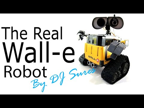
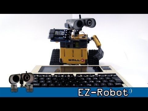
DJs The Real Wall-E
Its been a very crazy past few weeks. I took a day off today. Yes! I admit it. I took a day off... And I built a robot<img src=/images/emoticons/smiles.svg alt=:) class=emoji...
WiinterU |
robot
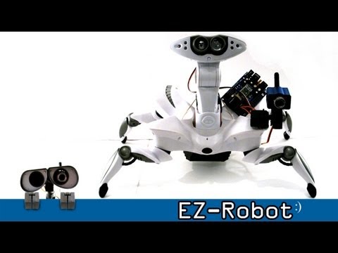
DJs Wowwee Roboquad
The WowWee RoboQuad makes for a perfectly affordable unique robot platform, with the aid of EZ-Robot. Description: After adding support for his WowWee RoboSapien, DJ continued on to...
WiinterU |
robot
DJs Multiple Robots With One Joystick
Demonstration how I controlled 6 robots with one joystick in my <a href="//synthiam.com/Community/Questions/1295" target=_blank...
WiinterU |
robot
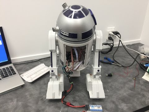
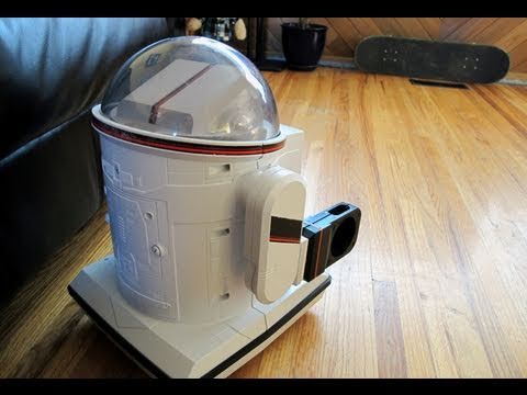
DJs Hasbro R2d2 Hacked With Iotiny
This build was in two parts. The original build was hacked live at Comic Expo in Calgary Alberta with an EZ-B v3 in 2012. It was a fun hack, because I...
Sproket |
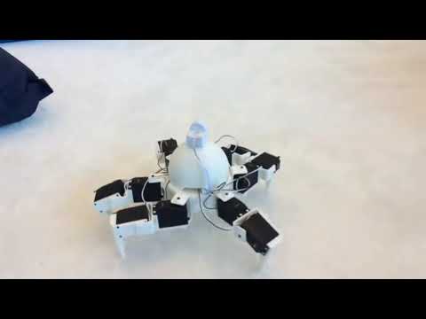
robot
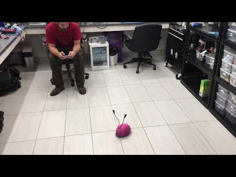
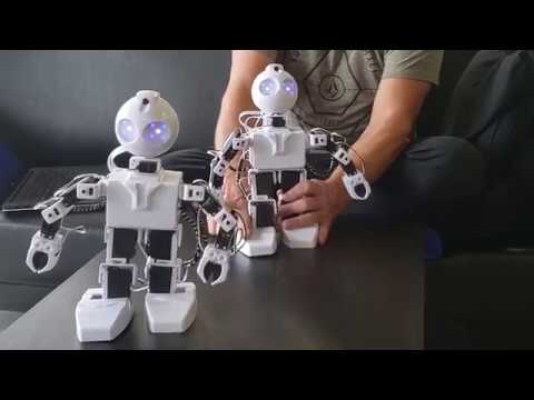
DJs Drd 3D Printable Robot
I wanted a robot that was super easy to 3D print and was least number of parts to make. This robot was inspired from the Farscape DRD robots. Theres merely 2 components...
Nink |
live hack
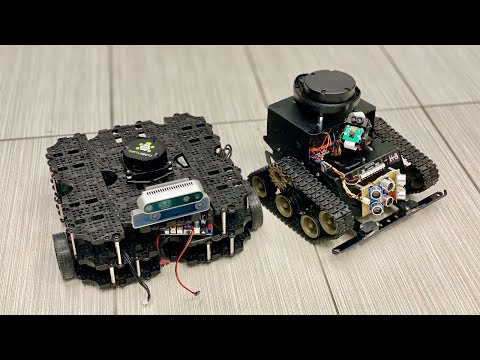
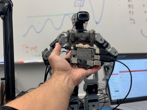
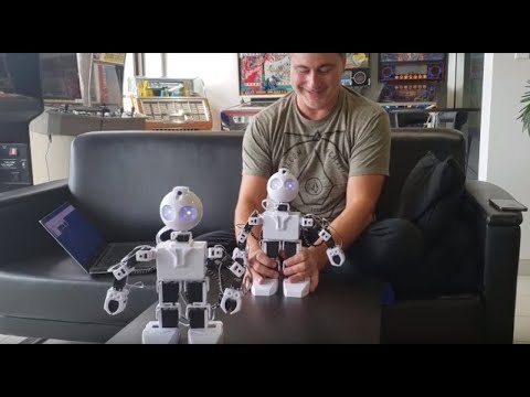
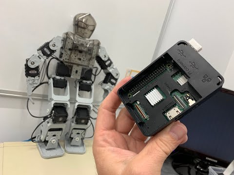
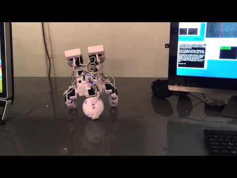
DJs Test Bots (Turtlebot 3, And K-8)
I will be upgrading my test robots with single-board computers (SBCs). Ill be adding the Intel Up Board and Rock Pi/x to each of the robots. The...
Herr Ball |
robot
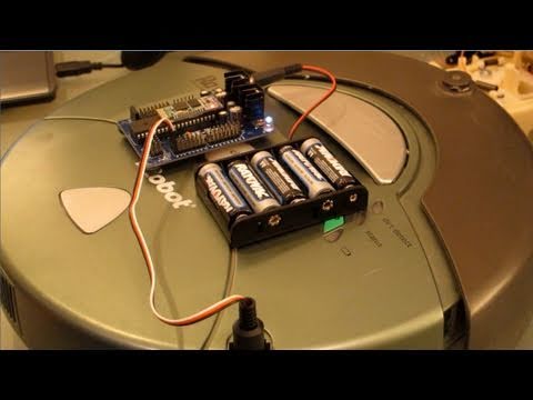
DJs Irobot Roomba Hack
DJ modifies an iRobot Roomba to be wirelessly controlled with the EZ-B. He also adds a webcam and voice recognition! This is all done by soldering only two wires from an old...
TMesserschmidt |
live hack
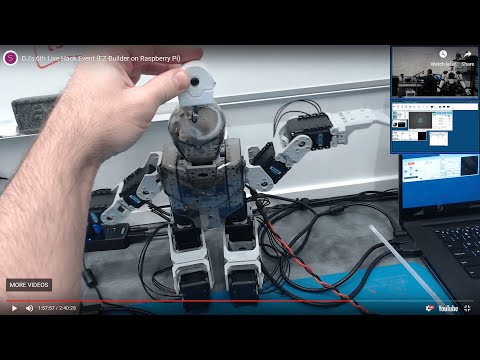
DJs 6Th Live Hack Event (Raspberry Pi & Neopixel With Arduino)
In this 6th installment of DJs Live Hack Events, well be installing EZ-Builder on a...
Synthiam Suppo… |
live hack
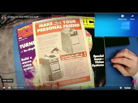
1983 Robot Magazines Show Robots Havent Changed
Take a trip with us into the past down memory lane - or - aka the time before now! We spend 3 and a half hours browsing 3...
robo rad |
robot

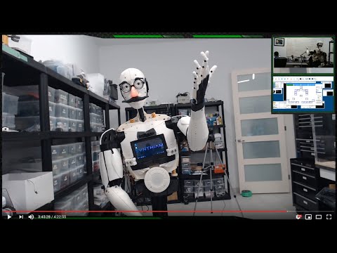
DJs DJ’S Test Platform (K8)
<a href="/uploads/user/DB763BE15E695777689418BE7364E0A3/krw5r3eo.jpeg" target=_blank><img class="img-fluid pt-1 pb-1"...
EzAng |
live hack
Robot Learn A New Object
Ill be using the camera and speech recognition to instruct the robot to learn a new object. Ill demonstrate how new objects can be taught and recognized. Well probably use...
robo rad |
live hack
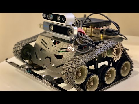
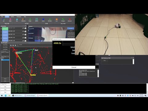
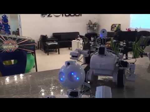
DJs K8 Intel Realsense & Navigation
Were going to play with the new robot that I have been re-building. Added the Rock Pi/x, Intel Realsense T265 & D435i, and the Sabertooth...
robo rad |
robot
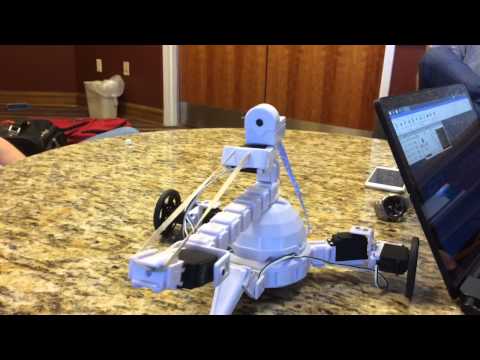
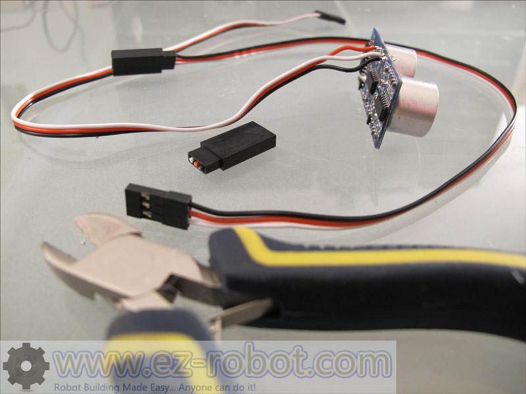
DJs Intel Realsense T265 Adventures-Bot Part 3
This is a test with the Intel RealSense T265 tracking camera for localization with the EZ-Robot AdventureBot. I use 3 ultrasonic...
proteusy |
live hack

A Little Of This, A Little Of That
Well take it as it goes tonight in this last-minute live hack event. My plan is to do a few things with the ESP32 Cam and see if we can get servos with...
DJ Sures |
live hack
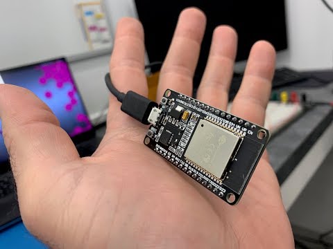
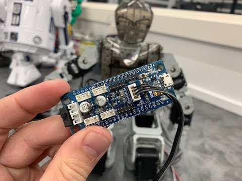
ESP32 Connect To ARC
Ill be programming the ESP32 Doit DevKit v1 with a firmware which turns it into an EZ-B for ARC to connect and control. Well hook up a servo and demonstrate how to move it. Maybe...
DJ Sures |
robot
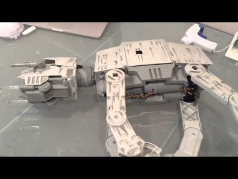
DJs Imperial AT-AT Walker Robot - The Force Is With Me!
This year i made a decision to get back into building robots. So, Ill start with this! Kind of ironic, an...
robo rad |
robot
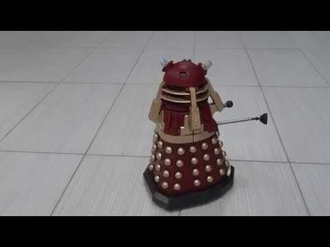
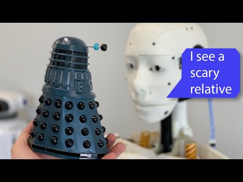
DJs Ez-B V4 Dalek
I built a Dalek EZ-Robot tonight. Well, i upgraded my EZ-B v3 hack to the v4 and added a few more servos. One to control the nose plunger thingy on their face up and down. And two other...
Nomad 6R |
robot
DJs Trs-80 Model 100 Controlled Wall-E
<div class="embed-responsive embed-responsive-16by9"><iframe class="embed-responsive-item"...
DJ Sures |
live hack
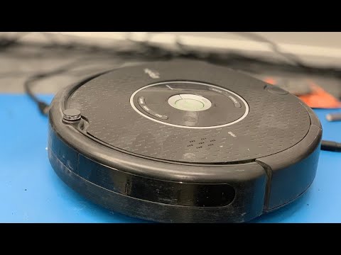
Irobot Roomba Live Hack
Gonna hack the iRobot Roomba and connect it to the ARC software... Making it into a real robot! Put a camera on it and all that jazz. Well be using the iRobot Roomba Movement...
robo rad |
live hack
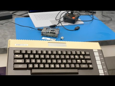
Atari 600Xl - Another Retro Game Night Hack
Last minute notice of my hack - and something a little different.<img src=/images/emoticons/smiles.svg alt=:) class=emoji /> Ill...
MaudDave |
live hack
The Lattepanda Robot Hack
Im hacking the lattepanda to control Robotis Dynamixel servos and use a USB camera for machine vision. This will be a fun hack because the LattePanda is a powerful robot...
cem |
live hack
Dimension Engineering Sabertooth & Kangaroo
Ill be connecting a Dimension Engineering Sabertooth to their Kangaroo and controlling via Synthiams ARC robot software. Well...
RoboHappy |
robot
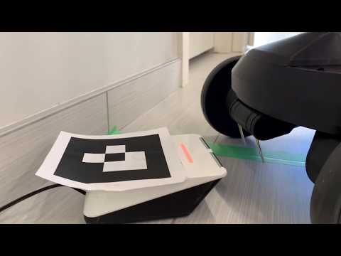
DJs Self Docking Robot
I used an Ohmnilabs Telepresence robot to write some self docking code as an example. I really like their docking mechanism, which uses magnets. Something like this can be...
jstarne1 |
robot
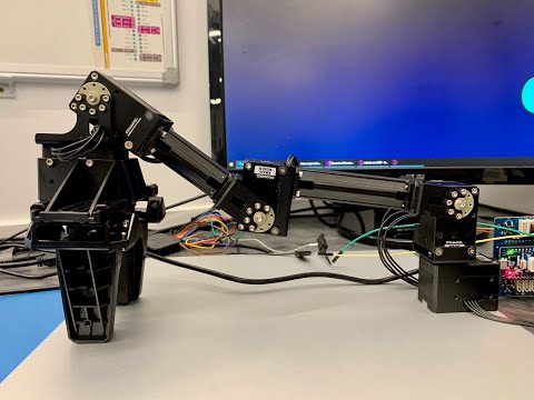
DJs Robotis XM430 Dynamixel Arm With Open CM9.04
I was using a robotis arm for picking stuff up - albeit nothing special, but thought the process might be useful to some...
Mickey666Maus |
robot
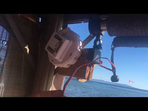
DJs Robot Blinds Control
Lazy much? Blind control to major tom... I can now control the blind/shades on my deck from my phone! With a little bit of hot glue, a couple wood screws and some pieces of...
DJ Sures |
live hack
Robot As Puppet To Control Another Robot By Reading Servo Positions
In this hack, Ill be showing how to control a robot with another robot as a puppet by...
WiinterU |
live hack
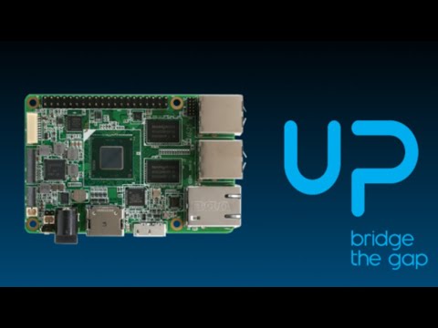
Intel Up Board As A Robot Controller
Ill be installing ARC on an Intel Up Board and demonstrating its capabilities as a robot controller. Ill start from a brand new installation of...
skidroe |
live hack

Exosphere Community Beta Live Q&A
DJ Sures will be introducing Exospheres community beta in a live Q&A session. Questions related to Exosphere are welcomed. Hell talk about why...
EzAng |
live hack
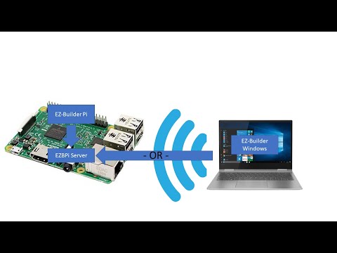
DJs 7Th Live Hack (Neopixel, Arduino, Raspberry Pi Ezbpi Server)
Todays live hack, well play with the Arduino and see if we can get it to control NeoPixels...
Steve Thurston |
live hack
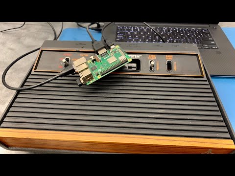
Raspberry Pi Hacking Atari 2600
A little different tonight, rather than hacking robots. Im a retro gamer at heart, and have been on a mission adding raspberry pi emulation to my retro game...
eran_p |
robot
DJs Robot Head
With an animatronic robot head, DJ created a new feature for ARC. This robot was used as a platform for the Relative Servo Tracking Camera Control option. Description: Animatronic companies...
robo rad |
live hack
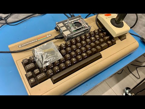
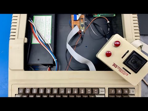
Commodore 64 Arduino/Raspberry Pi Hack! O_O
Last retro console hack before I get back into programming some robots. Im taking my original C64 breadbox that I grew up with and...
nallycat |
live hack
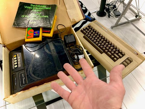
Hacking Decision... C64 Or Fairchild Channel F?
I know... I know... DJs hacking more game consoles again? Yup! I do love robots as much as you, but I also love distractions....
robo rad |
live hack
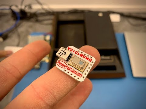
Hacking The Thermal Camera AMG8833
Ill be creating an EZ-Builder behavior control that receives and displays data from the Thermal Camera AMG8833. Itll be a long boring evening of...
robo rad |
live hack
DJs 9Th Live Hack - Raspberry Pi + Dynamixel... Together For Ever!
This is a short live hack where I will demonstrate how to... 1) Install EZ-Builder on...
Mickey666Maus |
robot
DJs Revolution Snake
I dived into the box fresh injection molded parts from our manufacturer tonight and built this EZ-Robot Revolution Snake! It uses a SIN wave for each servo position. <div...
RoboHappy |
live hack
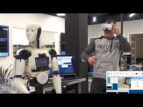
Live Hacking Microsoft Mixed Reality VR To Control A Robot
Ill be demonstrating how to control servos and see what the robot sees using a Microsoft Mixed Reality...
DJ Sures |
live hack
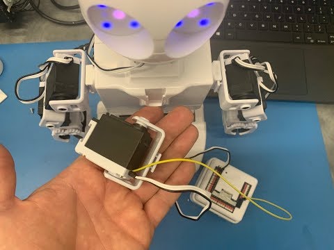
PWM Servo Position Feedback (Read Servo Position)
Ill be hacking a PWM Servo to have positional feedback for EZ-Builder using an EZ-B v4. You can also perform the same...
Mickey666Maus |
robot
DJs JD Humanoid Puppet
Credit for this robot idea goes to @Nink, who suggested it based on my <a href="//synthiam.com/Software/Manual/PWM-Servo-Feedback-18047" target=_blank...
DJ Sures |
live hack
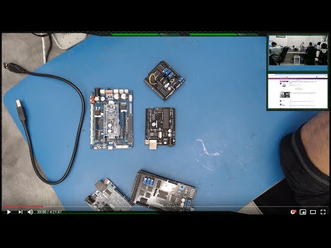
Djs 5Th Live Hack Session
In this 5th live robot hacking event, I will demonstrate how to program an Arduino and connect it to EZ-Builder via USB and Bluetooth. Ill also control a Robotis Bioloid...
Dave Schulpius |
live hack
Hacking Robotis Opencm 9.04 With Bioloid
I will be hacking the Robotis OpenCM 9.04 controller with EZ-Builder using a Bioloid. Well install the Arduino OpenCM library and connect to...
Mickey666Maus |
live hack
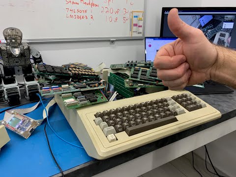
DJs Apple II Pi Hack (Part 2/2)
In this hack, Ill continue the Apple II conversion to the Pi. I created an Arduino PCB that converts the Apple II keyboard and 16 pin analog joystick to work...
DJ Sures |
live hack
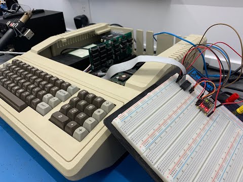
DJs Apple II Pi Hack (Part 1/2)
Remember my Apple II computer from a previous live hack event? Well, Im going to add a Raspberry Pi to its guts and use an Arduino to connect the Apple II...
DJ Sures |
live hack
DJs 8Th Live (Not) Hack... Were Playing Games!
I was sick with a massive head-cold and made it through without overdosing on NyQuil last week and skipped a live hack session....
JustinRatliff |
live hack
DJs 4Th Hack Event (Arduino, Bioloid, Lewansoul, And More)
In the last event, some people asked me to demonstrate how to use the LewanSoul Serial Servos. Also,...
fxrtst |
live hack
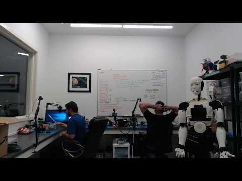
DJs Third Hack Night
Were going to play with EZ-Builder software, build Perrys robot eyes, make Dynamixel servo cables, demonstrate how to move dynamixel servos and record positions, and more! As...
robo rad |
robot
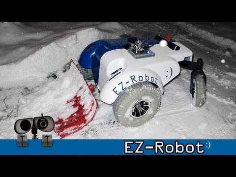
DJs How Do I Shovel My Snow?
With a robot, of course! What did you expect?<img src=/images/emoticons/smiles.svg alt=:) class=emoji /> This is a robot shell that I built with some students...
robo rad |
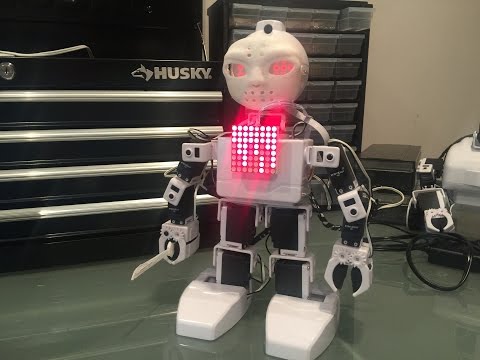
robot
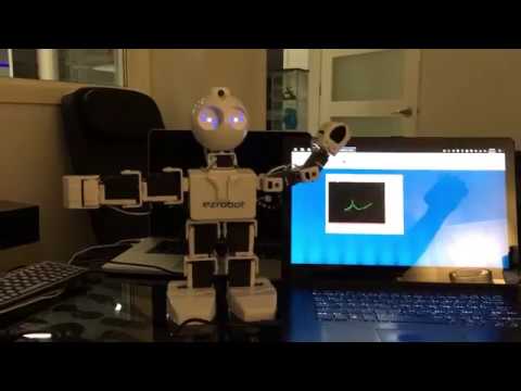
DJs Machine Learning And Cognitive Services Jd Humanoid Robot
We had been working on plugins for the Microsoft Cognitive Services, and I was testing them with...
DJ Sures |
robot
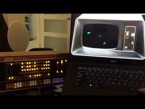
DJs And Now For Something Completely Different (Pdp-8)
This isn’t robot related... although I used ARC to make the software vc8e emulator. Read on... I’ve always been...
DJ Sures |
robot
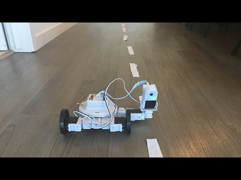
DJs Autonomous Robocar
Heres a robot that I built last year to follow the lanes of a small test track. This was built 24 hours before attending Chris Andersons <a...
mcsdaver |
robot
DJs Adventurebot Chasing Red Ball
Have you ever found something so hipnotic that you can sit and watch it for hours? Thats what happened to me after programming this <a...
DJ Sures |
robot
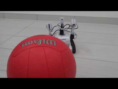
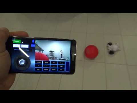
DJs Roli Rover Robot Chasing Red Ball
It seems that programming an EZ-Robot to chase a red ball is a popular exercise of mine. Ive done it with <a...
DJ Sures |
robot
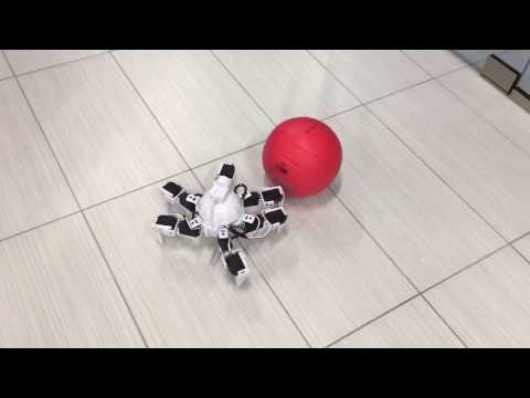
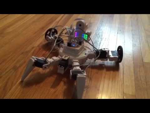
DJs Six Hexapod Robot Tracking Ball
This was a fun use of ARC to configure a <a href="//www.ez-robot.com/Shop/AccessoriesDetails.aspx?productNumber=30" target=_blank...
DJ Sures |
robot
DJs Jd Humanoid Controlled By Microsoft Kinect
Microsoft had sent me a Kinect a few years ago, and I embarrassingly finally got around to doing something with it. I created an...
DJ Sures |
robot
DJs DJs Omnibot 2000
I just finished a short video with clips of building my Omnibot 2000, you can watch it here. This robot contains all of the great new features of ARC - Wii Remote Control - Glyph...
DJ Sures |
robot
DJs Ips (Indoor Positioning System)
For quite a few years, ive been mentioning that I have been working on a positioning system for ez-robots. I guess its time that i share my...
Ellis |
robot
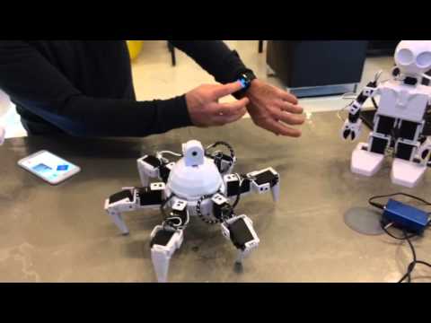
DJs Apple Watch Robot Control
Not sure how many of you have seen this, but we added Apple Watch support to the ARC iOS app! For the longest time, no one knew what an Apple Watch was good...
DJ Sures |
robot

DJs I Taught Jd To Serve Snacks
Did you know Im a huge fan of M&Ms? Only the peanut butter kind! Theres an event tomorrow at google (BotLuck), and my JD will be serving snacks. Download...
Dunning-Kruger |
robot

DJs Darth Vader Humanoid Robot
I made this Darth Jader for an upcoming The Robot Program episode. Wanted to share the robot exclusively with the ez-robot forum before the real episode goes...
Nomad 6R |
robot
DJs Omnibot TV Watching
The latest version of the EZ-SDK and ARC contains an enhanced motion tracking update. The quality and edge detection algorythm has been modified and seems to work great!!...
Toyhackrobotic… |
robot
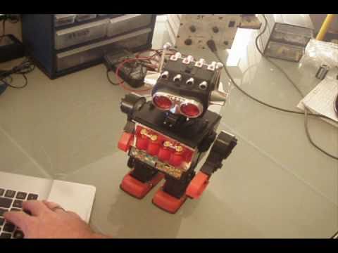
DJs Tomy Omnibot
This was probably the funnest robot I have created yet. It is a wicked platform with a lot of room to grow. Ive been adding sensors and programming to it ever since I got it. Project Page:...
Toyhackrobotic… |
robot
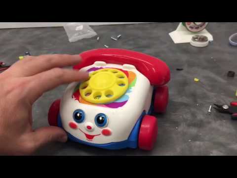
DJs Fisher Price Chatter
This is the strangest robot that Ive ever built... But i had to, can you blame me?<img src=/images/emoticons/happy.svg alt=:D class=emoji /> <div...
mstephens_42 |
robot
DJs Super Six Hexapod
You may have seen this video of a real large ez-robot hexapod... <div class="embed-responsive embed-responsive-16by9"><iframe...
DJ Sures |
robot
DJs Jds Friday The 13Th
Beware of the robots on Friday the 13th! <div class="embed-responsive embed-responsive-16by9"><iframe class="embed-responsive-item"...
proteusy |
robot

DJs Teddy Ruxpin Robot Version 1
I added a new robot today. It is a Teddy Ruxpin, if you remember him? He was a talking toy from the 1980s that used a tape player. His mouth and eyes were...
Nomad 6R |
robot
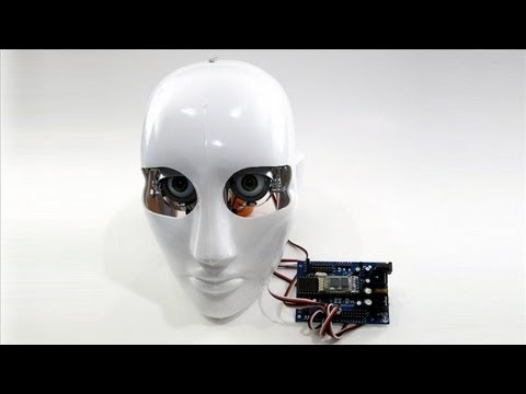
DJs Robot Head
I started on a little project for a humanoid-type platform. I have ideas for the body and such, but im starting with the head because im adding new features to ARC for it. <div...
Nomad 6R |
robot
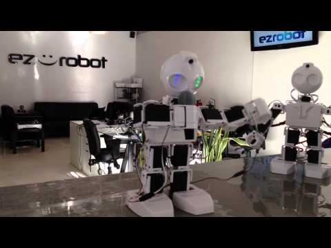
DJs At Home With Jd
I took the evening off to chill at home with JD for my first time :). I tweaked many of the existing motions to be more fluid and not as clunky, it was a lot of fun! I didnt know...
Nomad 6R |
robot
DJs Myo Gesture Tutorial
The MYO is a creative controller for interacting with your ez-robot. It uses gestures and an accelerometer to trigger actions, events and move servos. This tutorial...
Nomad 6R |
robot

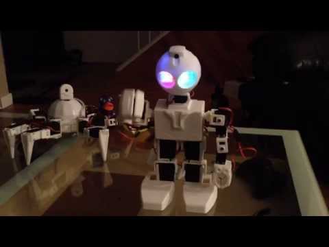
DJs Introducing Jd
JD finally gets a little introduction video... <div class="embed-responsive embed-responsive-16by9"><iframe class="embed-responsive-item"...
Dunning-Kruger |
robot
DJs Jd Wants His Rubber Duck
Should I give it to him? lol <div class="embed-responsive embed-responsive-16by9"><iframe class="embed-responsive-item"...
Nomad 6R |
robot

DJs Mobile App Developer Tutorial
So, youve built your ez-robot and now you would like to make your own mobile app. Did you know EZ-Robot has a robot appstore? And that you can easily...
DJ Sures |
robot
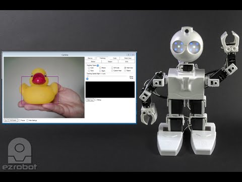
DJs Detect Multiple Colors
One of the features that makes ez-robot so special is the camera that can detect faces, objects, glyphs, qr codes and multiple colors. For this tutorial, we will use...
Nomad 6R |
robot
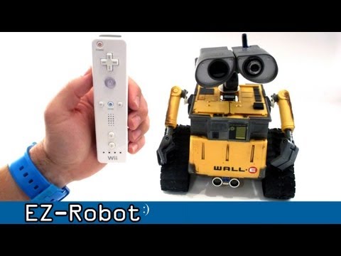
DJs Wii Remote Controlled Robot
Recently, Ive added a great deal of support to the Wiimote Control in ARC. This includes EZ-Scriptable buttons and a few other goodies. I set Wall-e to be...
Dunning-Kruger |
robot
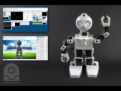
DJs ARC Overview
The ultimate robot software ARC is leading the way for the next generation of robotics. Heres a short video I put together to introduce some of the features. <div...
Aerius |
robot
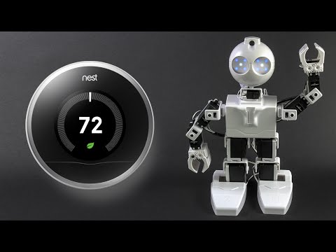
DJs Jd Connects To Nest Thermostat
I put this little tutorial and robot together to show how you can connect your JD to a Nest Thermostat. Its neat because you can be anywhere in the...
DJ Sures |
robot
DJs Elastic Band Shooter
In parallel with James <a href="//synthiam.com/Community/Questions/7604" target=_blank rel="nofollow">Elastic Band Turret</a> build, we were...
Nomad 6R |
robot
DJs Hey Jd, Need A Lift?
JD was a little lazy today... <div class="embed-responsive embed-responsive-16by9"><iframe class="embed-responsive-item"...
Steve G |
robot
DJs Taught Jd How To Somersault
Dont try this at home!<img src=/images/emoticons/happy.svg alt=:D class=emoji /> <div class="embed-responsive...
Nomad 6R |
robot
DJs I Shall Call Him Norm
Norm is a very fitting name, no? <div class="embed-responsive embed-responsive-16by9"><iframe class="embed-responsive-item"...
thetechguru |
robot
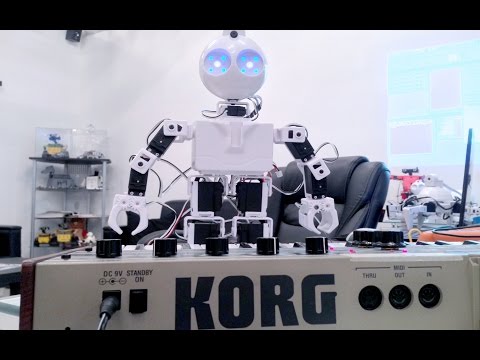
DJs So, I Taught Jd How To Play The Piano
This is just the first version... I think itll be a good idea to put a robot band together after the holidays<img...
Dunning-Kruger |
robot
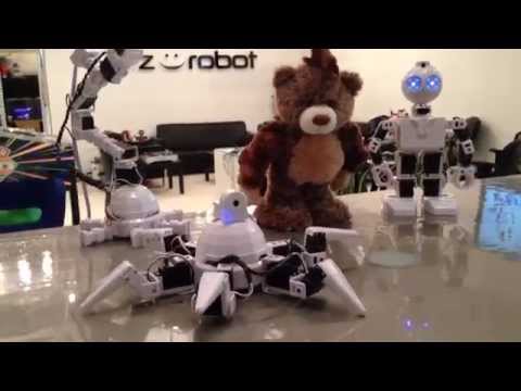
DJs Six Hexapod Demo Dance
Playing with the Six Hexapod tonight... thought I would share this<img src=/images/emoticons/smiles.svg alt=:) class=emoji /> <div class="embed-responsive...
VGosine |
robot

DJs Funny 3 Legged Robot
Some of the guys around the office were thinking of creative combinations today. I stumbled across their final "creation" this afternoon and wondered if I could...
Sudo the Banne… |
robot
DJs How About A Dance-Off?
Hey community, how would you feel about an ezrobot dance-off contest? Here is the STL file for the microphone:...
DJ Sures |
robot
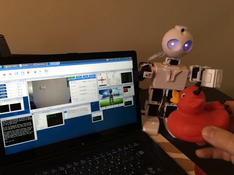
DJs Philo Junior Color Tracking Test
Hey there! I was playing around with the Philo Junior. This example uses the camera option "Track By Relative Position", in case anyone...
Nomad 6R |
robot
DJs Revolution. The History Of
I created this thread in the Project Showcase because, well, it was once a project... and now it is a company. Id like to tell you a little story about the...
stonewolf |
robot

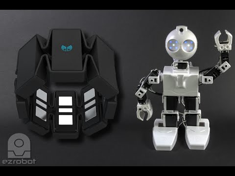
DJs Choose Your Ez-Robot!
I created a little video to summarize the current supported EZ-Robot Platforms - of course, this list will grow. Supporting existing platforms is great, but nothing beats...
DJ Sures |
robot
DJs Project: Scarab
I started a new project today... But I didnt get very far. I stopped right after I started because I decided to wait until next week to finish it. Solarbotics had asked me to do a...
Hazbot |
robot

DJs Ez-Robot Takes The Secret Challenge Competition
EZ-Robot is sponsoring a team of awesome children to build a robot to compete in the <a...
LJ |
robot

DJs Brookstone Rover
DJ saw the potential of the Brookstone Rover right away. Adding support into his ARC software greatly enhances this product - from a boring remote control toy, to a full-featured...
DJ Sures |
robot
DJs Tomy Omnibot V1
This was an exciting project that DJ Sures had been planning for weeks. He purchased the Tomy Omnibot off Ebay and started hacking it within hours from the post office. He modified...
DJ Sures |
robot

DJs Cyborg Snowman
What do roboticists do when it snows? Click to find out<img src=/images/emoticons/smiles.svg alt=:) class=emoji /> Description: We had a big snowfall in Calgary Canada this...
DJ Sures |
robot
DJs Master Blaster Robot
DJ Sures named this robot Master Blaster. Dont ask us why, he still doesnt know. But hes pretty simple and is remote controlled. He has no sensors for object detection, so...
DJ Sures |
robot
DJs Teddy Ruxpin Robot V1
DJ Sures built this Teddy Ruxpin Robot from a toy that he purchased off Ebay. The toy was broken, so he didnt feel bad taking it apart (or cutting off his head). But, you...
DJ Sures |
robot
DJs Scarab Creepy Robot
Some people say this is creepy... Others think hes cute. You be the judge<img src=/images/emoticons/smiles.svg alt=:) class=emoji /> <br /> This was a remote...
DJ Sures |
robot
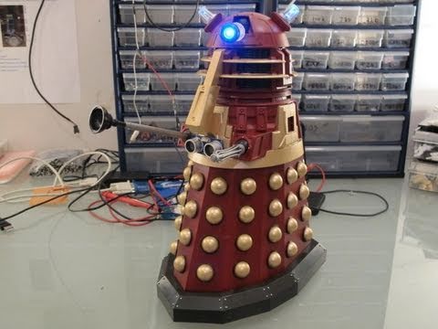
DJs Dalek
Are you familiar with Doctor Who? The longest running Sci-Fi TV show from Britain! Some would argue who is the Doctors worst enemy... Is it the Cybermen? Daleks? The Master? DJ Sures is certain the...
DJ Sures |
robot

DJs Robot Dog Chases Ball
Are you allergic to dogs? Well DJ Sures is! So whats the next best thing? Thats right, a robot dog that chases red balls. Description: What to do when you are allergic to...
DJ Sures |
robot
DJs Omnibot 2000
Standing 26 inches tall, the Omnibot 2000 was the latest from Tomy in their series of Omnibots. DJ got hold of a damaged one off eBay and converted it into a Personal Robot - One which can...
DJ Sures |
robot
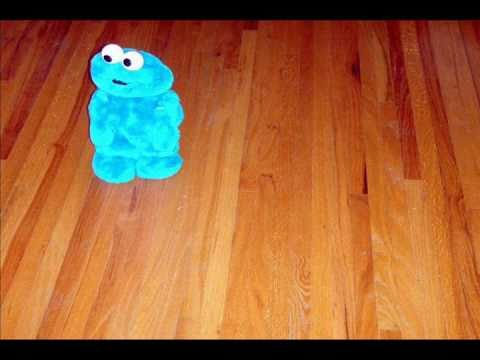
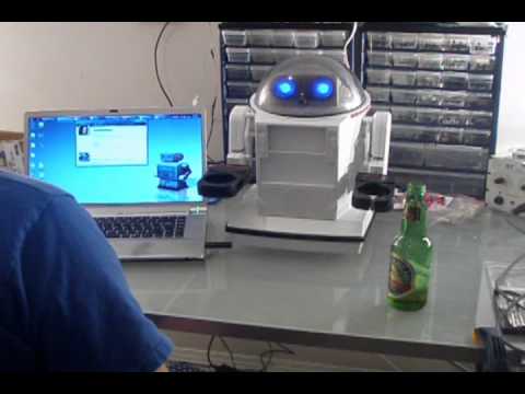
DJs Voice Recognition Robot
Re-using the Cookie Monster shell to show off the EZ-Bs Voice Recognition ability. This robot will respond to voice commands. Description: You may have seen this...
DJ Sures |
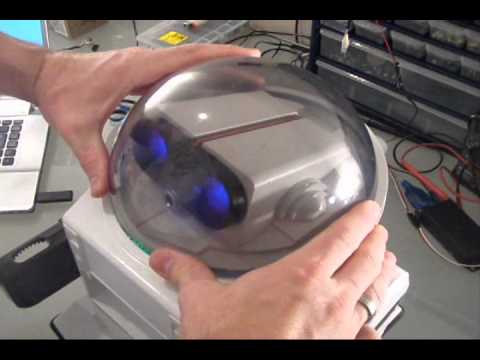
robot
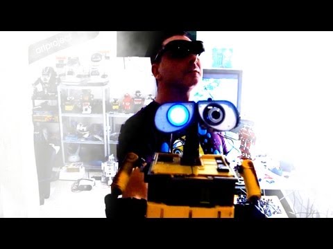
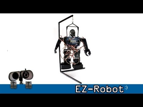
DJs The Real Wall-E
DJ Sures has made a few Wall-E mods in the past, but this one is sure to be unique! DJ added a camera and a vertical servo to Wall-Es head. With these new additions, EZ-B and ARC,...
DJ Sures |
robot
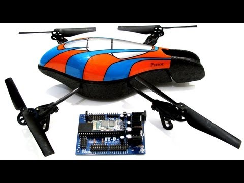
DJs AR Drone Parrot
DJ connects the AR Drone Parrot to ARC and has it chase a red ball around the room. This adds many great new features to your already awesome AR Drone Flying Robot! Description: DJ...
DJ Sures |
robot

DJs Vision Tracking Robot
This is a test robot DJ Sures created to trial a new module that he has been working on. It tracks and follows objects by their color. This robot was sadly never given a...
DJ Sures |
robot

DJs Cookie Monster Robot
A few years ago DJ Sures had built a Cookie Monster robot that ran on its own with 2D autonomous programming. Today DJ had removed the old circuit board and replaced it...
DJ Sures |
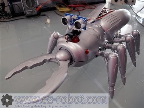
robot

DJs Spider Robot
This robot uses two DC motors instead of modified servos. The ADC Distance Sensor detects objects and the autonomous mode has many random delays for a jerky spider movement. Description:...
DJ Sures |
robot
DJs Robophilo
The RoboPhilo Junior is a fantastic and affordable Humanoid Platform for the EZ-Robot Complete Kit. Description: The RoboPhilo Junior is a fantastic and affordable humanoid platform. The...
DJ Sures |
robot
DJs Snow Shovel Robot
DJ Sures builds a robot that he equips with a shovel. The robot shovels outside in the cold, while DJ stays warm inside. Description: DJ Sures from EZ-Robot builds a robot that...
DJ Sures |